University of North Carolina at Chapel Hill
Campus-wide Energy and Utility History
25+ years of successful planning and implementation.
Since 1991, numerous planning activities for UNC’s utility systems have resulted in orderly and reliable expansion, with continuing focus on system efficiency and sustainability. Operating multiple utility generation plants as one virtual system, interconnected through a looped network of underground piping, has been a signature element of UNC’s utility systems. This includes two steam production plants, four chilled water plants, and three electric substations. Some of the AEI’s major implementation projects have been:
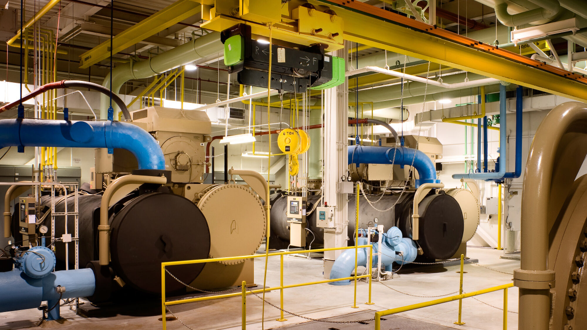
North Chiller Plant Renovation:
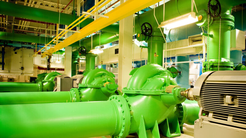
Reconfiguration of the existing plant with the existing footprint removed smaller, less efficient centrifugal chillers and replaced them with four 2,250-ton variable speed electrical centrifugal chillers. Plant capacity thereby increased by 4,500 tons and resulted in installed plant capacity of 17,000 tons.
The entire plant was designed as “fully variable,” with VFD’s driving all major motors, including the chiller compressors. The system was also designed with a variable primary pumping arrangement, further reducing the operating costs. This highly efficient configuration led UNC to operate the North Chiller Plant as their lead plant, achieving “all in” chiller plant efficiencies of 0.30 kw/ton in the winter months. Additionally, the plant has impacted overall system efficiency, reducing total annual energy consumption of the chilled water system to approximately 0.60 kw/ton from performance levels prior to system and efficiency improvements.
Landfill Gas Power Generation
This project created a landfill gas (LFG) collection system, an LFG engine generator, and a three-mile pipeline connecting them. A collection of wells drilled deep into the Orange County Landfill collects methane-rich LFG. Fans draw the gas to a treatment and conditioning system – including leachate cleanout risers and headers, and condensate traps – and compressors to pressurize the gas for distribution to the generator. There LFG powers a 20-cylinder combustion engine producing 1,000 kW of electrical energy that feeds the Duke Energy grid. AEI assisted with solid waste, air, and other environmental permitting. Planned addition of heat recovery will supply heat to future Carolina North Campus buildings
Manning Substation Upgrade
AEI designed the upgrade to replace aging 15kV switchgear and provide additional switchgear to complete a ring bus topology and add additional feeder circuits to accommodate future growth. Modification and testing of the closed transition operation was closely coordinated with the local utility for the 100kV transmission service. The design increased station battery controls, added a battery monitoring system, and augmented the campus SCADA system. The 15kV switchgear was specified to be arc-resistant ANSI Type 2B with additional safety features including bus differential protection. The design designated space and features for a future tie-in of 15MW of local cogeneration from a combustion turbine for distributed generation.
Cobb Chiller Plant
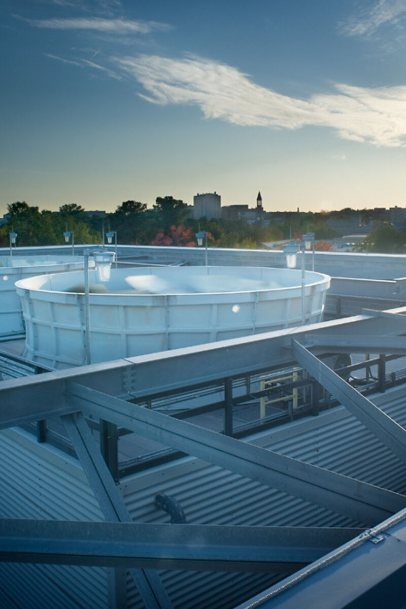
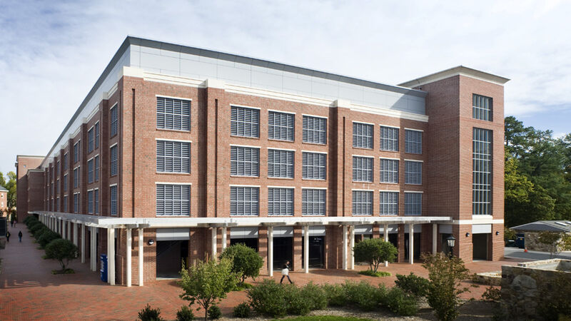
AEI was lead designer for this 10,000-ton plant coupled with a 460 space parking deck and over 7 acres of site redevelopment for the new facilities and adjacent recreational athletic courts. The chiller plant is equipped with five 2,000-ton, electric centrifugal type chillers, field erected counter-flow type cooling tower cells, and related auxiliary systems. Full height walls screen the towers from view and shield the nearby residence halls and nationally registered historic cemetery from noise emissions. The electrical system includes four medium voltage feeds to two high-speed, 6-way, pad-mounted switches located in a covered transformer yard. The transformer yard consists of five 2500 kVA transformers at 4160 volt, two 2500 kVA transformers at 480 volts, and a 1500 kVA transformer for the parking garage lighting and elevators.
The project included installation of 6,200 feet of chilled water distribution piping, completing critical loops in the campus distribution system as well as distributing chilled water from the plant. 7,500 feet of electrical duct bank was installed, connecting to the South Substation to provide additional capacity and redundancy for the plant and other sections of north campus. Routing along a major state road required coordination with NCDOT and the Town of Chapel Hill. AEI also provided commissioning services.
- 7+
- miles, steam and hot water distribution
Cogen Tunnel Replacement and Gilsulate Replacement
AEI evaluated a circa-1939 walkable steam tunnel and subsequently designed a 2,500-foot replacement tunnel from the cogeneration plant to the main campus, along a narrow railroad corridor lined with private residences. Concurrently, AEI directed the replacement of 10,000 LF of failing underground steam and condensate piping insulated with powder-type Gilsulate. New piping systems were installed in inaccessible precast and cast-in-place concrete tunnels. Projects required detailed coordination with campus entities, NCDOT, Town of Chapel Hill, and the Norfolk-Southern railroad, and integrated landscape and storm water upgrades from original conditions. On completion, these projects helped reduce energy consumption, cutting piping system heat losses from 14-15% of annual steam production to 7-8%.
South Chiller Plant, Phases I, II, III and IV
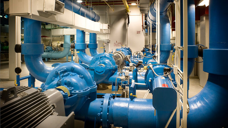
Four-step expansion of an existing 4,000-ton chiller plant to 25,000 tons. Phase I included two 1,500-ton steam absorption chillers, one 2,000-ton electric centrifugal chiller, and three 3,300-ton counterflow cooling tower cells. Phase II included two 2,000-ton electric centrifugal chillers and three 3,300-ton counterflow cooling tower cells. Phase III added an additional 6,000 tons and Phase IV included a 5 million-gallon, 40,000 ton-hour, chilled water thermal energy storage (TES) system, and 6,000 tons of additional capacity. Improvements in overall system delta-T increase storage capacity to almost 55,000 ton-hours at peak summer conditions. During periods of high electric pricing, load shift via TES has realized significant economic benefit to utility power purchasing on an hourly-price basis.
- 3+
- miles, primary power and telecom duct banks
Hot Water System Upgrade
Replacement of existing central heating and domestic services to 40 buildings in the heart of main campus, divided into three separate project areas. Area 1 created district heating and domestic hot water systems to serve 18 residence halls on the northeast side of campus. Areas 2 and 3 replaced the central heating hot water system for 22 academic buildings and residence halls on the historic north side of campus.
